CHOOSING THE RIGHT CABLES
Posted on Fri 06 May 2011 in Computer Music
Cables, cables, everywhere! But with so many different types, which ones do you need? And what is the difference between them all? Fear not, for I am here to explain everything… Plus, this guide also features an easy-to-understand description of the terms 'balanced' and 'unbalanced'.
CONTENTS
1. Introduction and Contents
2. 1/4" Jack
3. Balanced vs Unbalanced Audio
4. Why ground?
5. Mini-jack
6. XLR
7. RCA/Phono
8. USB/USB 2.0
9. Firewire 400 and 800
10. MIDI
11. TOSLINK
2. 1/4" Jack
THE 1/4" JACK
The 1/4" Jack Connection
Let’s start at the beginning, with probably the most common type of audio connection, the 1/4” jack!
A 1/4” jack socket simply looks like a circular hole that is 0.25 inches in diameter, e.g:

Sometimes 1/4" jack connections are combined with XLR connections. These sockets are called jack/XLR combo connections, and they look something like this:

In the case of the above connection, the 1/4" jack cable head slots in the central hole.
The 1/4" Jack Cable
The 1/4” jack cable head takes two forms, unbalanced and balanced, both of which look very similar.
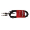
Here is an example of an unbalanced 1/4" jack head:

... and here is what a balanced 1/4" jack head looks like:

Both cable heads look extremely similar, but there is a difference between them! If you look carefully, you will notice that the unbalanced 1/4” connection features a single black band near the tip, whereas the balanced 1/4” jack connection features a second black band a little further down. If you want to learn why balanced jack cables feature an extra black band then please refer to the next page of this guide, entitled 'Balanced vs Unbalanced Audio'.
Where are 1/4" Jack Cables/Connections Used?
You will see 1/4” jack connections used for a number of different audio purposes. They are commonly used for line inputs and outputs on devices such as audio interfaces, synthesisers and mixers and they are also used for guitar inputs, and as inputs on some studio monitors. You may also see them used as headphone connections on some professional audio equipment (don't confuse the 1/4" jack with the mini-jack (page 5)) and even as microphone input connections on devices such as some DJ mixers. The truth is that they are used for lots of things, so the key is to familiarise yourself with what they look like so you can easily identify what type of cable you need for any given situation.
Buying a 1/4" Jack Cable
If you have identified that you need a 1/4" jack cable, then there are a huge variety of products out there to choose from. The main points to consider are:
1. What type of connection does the other device have? If it also has a jack connection then a simple 1/4" jack to 1/4" jack cable will do. But if it has a different type of connection (e.g. XLR), then you will need to select a cable with an appropriate second head.
2. Will you be running a balanced or unbalanced signal? If you want to run a balanced signal, then make sure that the 1/4" jack connection on your device is capable of transmitting a balanced signal. If you are unsure what the difference is between balanced and unbalanced signals, then please refer to the next page of this guide, entitled 'Balanced vs Unbalanced Audio'.
3. How long do you need the cable to be? If you are just running the cables between devices on a desk then you will probably only need cables that are 1-2 metres in length, or less. However, if you are running cables across a live stage, then you will probably want to purchase something substantially longer. Just remember that the longer the cable, the more noise your signal is likely to pick up, so the general rule is to pick the shortest cable length possible for the job at hand (i.e. if you only need to route audio a couple of metres, don't buy a 20 metre cable!)
3. Balanced vs Unbalanced Audio
BALANCED vs UNBALANCED AUDIO
When considering balanced and unbalanced audio signals, let's firstly revert back to our 1/4" jack example (see previous page), and consider why a balanced 1/4" jack features an additional black band across its head...
As you should have learned from the previous page (1/4" Jacks), an unbalanced jack head features one black band on the connection head. This band actually splits the connection into two separate parts using a material that does not let electrical signals pass through it (an insulator). These separate sections are known as the Tip (the very end of the connection) and the Sleeve (the main shaft of the connection), and because of this, such connections are sometimes referred to as TS connections (Tip Sleeve). As these sections are completely separate from each other, the cable can therefore be used to carry two independent signals.
With unbalanced jack cables, the Sleeve is usually used to carry the ground signal, and the tip is used to carry the mono audio signal (a single signal). The only problem with unbalanced signals is that as you may well know, wires are highly susceptible to noise interference (especially from neighbouring electronics and cables), and the longer the cable, the more interference it is likely to pick up along the way… unbalanced signals have no way of dealing with this problem, so if your cables pick up some interference, the equipment receiving the signal will have no way of distinguishing the clean audio signal from the noise, and so will just amplify everything, usually making the noise annoyingly audible!
However, on a balanced jack cable we have three separate sections: Tip, Ring and Sleeve (TRS). When using a TRS cable, we have two choices. We can either use it to transmit a ground signal (along the Sleeve), and an unbalanced stereo audio signal (left channel along the Tip, and right channel along the Ring), or we can do something extra clever, and use the cable to transmit a balanced mono signal.
A balanced signal essentially seeks to eliminate any noise interference picked up along the signal path, allowing you to transmit cleaner, more detailed signals throughout your set-up. In this case, the Tip of the 1/4” balanced jack connector is used to carry the original audio signal, and the Ring is used to carry an inverted version of the signal. The idea is that these signals travel through a pair of twisted wires within the cable, and each of these wires will pick up a very similar amount of noise interference along the way. Once both signals reach the other end, the inverted signal is then re-inverted so that it is now in perfect phase with the original signal, and when summed together creates an even stronger signal. However, by doing this, the noise signals are then in inverted phase, and as such cancel each other out! Check the simplified diagram below if you found this a little confusing, as it is often a little easier to understand with pictures:
1. The transmitting device produces an audio signal:

2. The signal is split between the Tip and Ring of the balanced connection:

3. The Ring signal is inverted:

4. Both signals are transmitted down the two twisted wires of the balanced cable:

5. As the signals travel down the wires, they pick up interference (noise) along the way, which is present in the signals picked up by the receiving device:

6. The Ring signal is then re-inverted:

7. The Tip and Ring signals are then re-combined. Because the original audio signals are IN phase, the two signals add together to make it even stronger. Because the noise signals are in inverted phase, when the two signals are added together, they cancel each other out to eliminate the noise!

So hopefully you now have a good idea of the difference between balanced and unbalanced connections, and understand why balanced connections are always preferable in professional audio situations. One thing to note though is that just because you are using a balanced cable doesn’t necessarily mean you are transmitting a balanced signal… you also need to make sure that the equipment you are using provides a balanced connection! You can usually find this information in the product specification if you are unsure.
If the equipment only supplies an unbalanced output, then it doesn’t matter if you plug in a balanced cable… you won’t cause any damage… it just won’t transmit a balanced signal! And the same applies if you plug an unbalanced cable into an balanced socket!
4. Why ground?
WHY DO AUDIO CABLES NEED A GROUND CONNECTION?
Analogue audio signals are essentially just a voltage that constantly changes in relation to the ‘shape’ of the sound it is representing. As such, analogue audio equipment requires a reference signal of 0V that it can compare the analogue signal to, to determine whether it is positive or negative, and how strong the signal is. Designers of analogue equipment achieve this by creating one point in the unit that deals with creating a constant 0V level, and they call this ‘ground’. With this in place, all voltages within the equipment can then be measured against it.
When you connect two pieces of electrical equipment together, they have to both agree on this reference point, so what do you do? That’s right, you connect both reference signals together to tie them in one place!
5. Mini-jack
MINI-JACK
The Mini-Jack Connection
As the name suggests, mini-jack connections are just like 1/4” jacks, but they are much smaller!
A mini jack connection looks like this:

The Mini-Jack Cable
Mini-jack cables look like this:

Where are Mini-Jack Cables/Connections Used?
You will probably be familiar with mini-jack connections from headphone sockets on consumer electronics such as home stereos, MP3 players and computer. Many professional headphones also use mini-jack connections, but come with 1.4” jack adapters to allow you to connect them to a number of professional electronics devices.
Note that although mini-jacks usually employ TRS connections, they are usually used to carry 2 unbalanced signals (a stereo signal) rather than a single balanced signal.
Mini-jack connections are also sometimes used on optical (TOSLINK) cables to route digital data into a device. For more information on this, please refer to page 11 - TOSLINK.
Buying a Mini-Jack Cable
The main thing to be wary of when buying a mini-jack cable is that they come in a variety of sizes, most commonly 1.5mm, 2.5mm, and 3.5mm. The most common size for a standard mini-jack headphone socket is 2.5mm - this is the connection that is most likely to feature on your MP3 player/iPod and computer/laptop, but it is always worth double checking the exact size before making a cable purchase.
6. XLR
XLR
XLR cables are also very common in professional audio equipment… this is because they also transmit a balanced signal, and can be locked into place to form an extremely sturdy connection.
The XLR Connection
An XLR female socket looks like this:

…or something like this when combined with a 1/4” jack connection:
…or like this when combined with a ¼” jack connection:
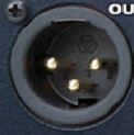
 However, you may also see some audio equipment with male XLR connections, which look like this:
The XLR Cable
The cable that plugs into the female XLR socket is called a male XLR connection, and it looks like this:
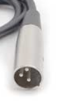 And you probably guessed it, but a female XLR connection is required to plug into a male socket:
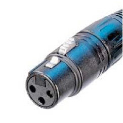 The XLR Connection/Cable – Where are they Used?
Female XLR connections (requiring a male cable connection to attach to) are commonly used to connect a microphone to an audio interface or mixer, or to input an AES/EBU digital signal.
Male XLR connections (requiring a female cable connection to attach to) are commonly found on microphones and for AES/EBU outputs for sending digital audio data.
7. RCA/Phono Cables
[RCA Cables / Phono Cables]
What’s the difference between RCA and phono cables? The answer is… nothing! They are just different names for the same thing, so no need to be confused with the different terminology. And if you fancy some (probably useless) knowledge, then RCA stands for Radio Corporation of America!
The RCA / Phono Connection
RCA sockets look something like this:
The RCA / Phono Cable
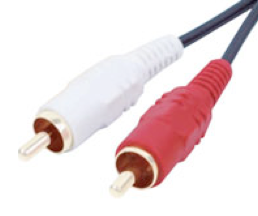
… and an RCA cable looks like this:
The RCA / Phono Connection/Cable – Where are they Used?
RCA connections are again used for a number of different things. Firstly, you may see them used for inputs and/or outputs, where they are being used to carry unbalanced mono analogue audio signals. A common piece of equipment that employs such connections is a DJ turntable.
However, RCA cables may also be used to carry stereo digital audio data using a S/PDIF connection. When routing audio in this way, it is recommended that you use a 75 Ohm RCA cable to ensure you get the best possible sound quality.
8. USB / USB 2.0 Cables
[USB / USB 2.0 Cables]
The USB / USB 2.0 Connection
There is no difference between the appearance of USB and USB 2.0 connections; it is all down to the devices themselves and what protocol they use.
The USB / USB 2.0 socket featured on computers looks like this:
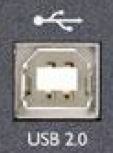
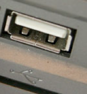 … and the socket featured on an audio device is likely to look like this:
… although you may also see some devices with mini-USB connections:
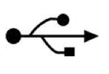
 If you are unsure as to what a connection is, then look for the universal USB symbol or read the product’s manual:
The USB / USB 2.0 Cable
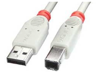
USB cables come in various forms depending on the types of connections you need to attach to. The most common lead needed to attach a USB device to your computer will look like this:
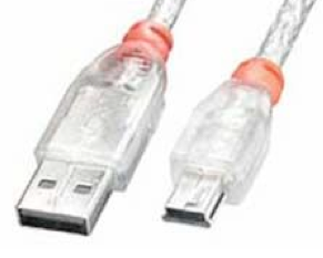
However, occasionally you may find that a device (such as an external hard drive) features a mini USB socket, in which case you will need a cable such as this one:
Appropriate USB cables usually come with the device that you are connecting to your computer (e.g. an audio interface), but there may be situations where you need to buy a new one, e.g. if your cable breaks or if you require a cable of longer length.
The USB/USB 2.0 Connection/Cable – Where are they Used?
USB / USB 2.0 cables are used to connect two devices together so that they can communicate data with each other using the USB or USB 2.0 protocol. In most situations this will involve attaching a device to your computer, such as an audio interface, a MIDI controller, or an external hard drive.
Extra Information: What is the difference between USB and USB 2.0?
The main difference between both these protocols is transfer speed. USB (or USB 1.1 as it is technically known) transfers data at a maximum speed of 12 Mbps (Mega bits per second), whereas USB 2.0 operates at an ultra-high maximum speed of 480 Mbps – that’s 40 times faster!
9. Firewire Cables
Firewire cables
The Firewire Connection
Firewire connections come in two different forms; Firewire 400 and Firewire 800.
A Firewire 400 (6-pin) socket looks like this:
 In some cases you may also see small Firewire 400 (4-pin) sockets that look like this:
A Firewire 800 (9-pin) socket looks like this:
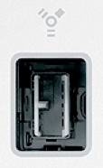
If you are unsure as to what a connection is, then look for the universal Firewire symbol or read the product’s manual:
Again, the specific cable you will need to connect two Firewire devices together will depend on what protocol each device utilises.
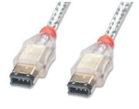
To connect two Firewire 400 devices together, you will need a cable with a Firewire 400 connections on each end:
To connect two Firewire 800 devices together, you will need a cable with a Firewire 800 connections on each end:
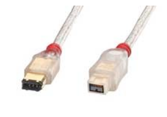
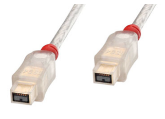 And if you want to connect a Firewire 800 device to a Firewire 400 device or vice versa? That’s right! Simply purchase a cable with a Firewire 800 connection on one end and a Firewire 400 connection on the other:
And of course there may also be times where you need to connect to a Firewire 400 4-pin socket, in which case you will need to look for a cable with a 4-pin connection on one end, and the appropriate connection on the other end (this example picture uses a Firewire 400 6-pin connection):
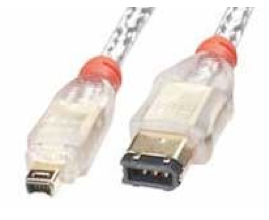 Just note that the cable will not have any effect on the speed of data transfer. If you have a Firewire 400 device connected to a Firewire 800 port, it will still only transfer data at Firewire 400 speeds.
The Firewire Connection/Cable – Where are they Used?
Firewire cables are used to connect two devices together so that they can communicate data with each other using the Firewire 400 or Firewire 800 protocol. In most situations this will involve attaching a device to your computer, such as an audio interface, a MIDI controller, or an external hard drive.
Extra Information: What is the difference between Firewire 400 and Firewire 800?
The main difference between both these protocols is transfer speed. Firewire 400 transmits data at a constant 400 Mbps, and Firewire 800 transmits data at an impressive 800 Mbps!
10. MIDI Cables
MIDI cables
The MIDI Connection
MIDI connections look like this:
THE MIDI CABLE
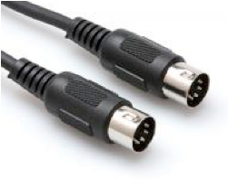
The MIDI cable looks like this:
Notice how MIDI cables are exactly the same on either end, hence it does not matter which way round you connect a cable. The main rule when connecting MIDI cables is to connect the MIDI Out from one device to the MIDI In on of another device and vice versa to ensure that they have bi-directional communication with each other. Note, there are situations using multiple MIDI devices where your connections may not be quite this simple, but that is the general rule.
The MIDI Connection/Cable – Where are they Used?
Surprise, surprise, MIDI cables are used to connect two MIDI devices together! Although MIDI communication with your computer can now be achieved via USB or Firewire connections, equipment such as MIDI interfaces, hardware synthesisers, and MIDI controllers generally feature standard MIDI connections so that they can all connect together.
12. TOSLINK Cables
TOSLINK Cables
The TOSLINK Connection
The TOSLINK connection looks like this:
Note that input and output TOSLINK connections are exactly the same… so be sure to check the labels for each (IN and OUT) when connecting a device up to them.
The TOSLINK Cable
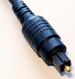
The TOSLINK cable looks like this:
The TOSLINK Connection/Cable – Where are they Used?
TOSLINK cables are optical cables, and can be used to transfer digital audio between devices that offer the relevant connections. You will find them on some audio interfaces, some CD and DVD players, as well as DAT recorders and some computers.
Thanks for reading and happy cable shopping!
